+44(0)1424 739 622

Packaging Material Testing FAQs

Table of Contents

FAQ Categories

Who measures slip/friction?

Friction testing is used in the packaging industry to measure the slip resistance of a product, with the aim of predicting feeding and running speed on an automatic glueing, erecting, filling or packaging line.

Other industries that test for slip include the paper industry (e.g. for the automatic feeding of envelopes and banknotes) and plastic manufacturers (the frictional properties of packaging films).

What is slip/friction?

A products slip resistance is characterised by its coefficients of friction:

Static coefficient of friction = Fs/N

Dynamic coefficient of friction = Fd/N

Where Fs is the maximum static frictional force and Fd is the average dynamic frictional force. N is the Normal force, ie the force of gravity acting on the sample and test sled.

In practical terms, the static slip relates to the force required to get two resting surfaces moving, dynamic slip is the smaller force that is required to keep the surfaces moving once this initial “inertia” is overcome.

These values are expressed as ratios and do not have units, they are usually quoted as a decimal value between 0 and 1, for example, a surface might have a static slip coefficient of 0.35 and a dynamic slip coefficient of 0.18.

How is Coefficient of Friction measured (COF)?

All methods of COF measurement involve preparing a sample into two flat pieces, the samples are placed together and a constant weight is applied to represent the normal force. One piece is fixed, and a gradually increasing force is applied to the second sample until the samples begin to slip against one another (Fd Max).

How to measure friction

Horizontal Plane (flatbed) Friction Testing

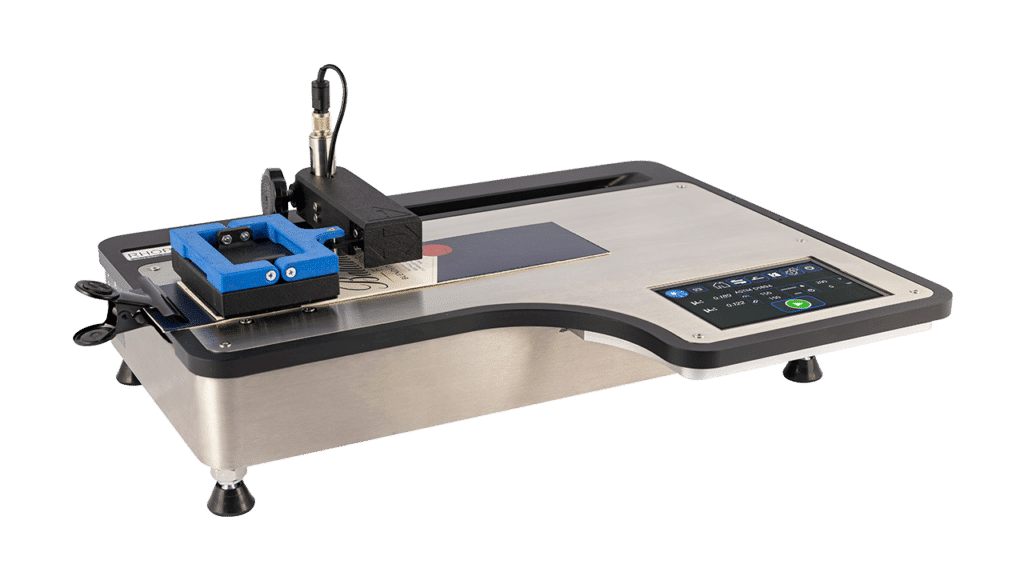
To measure Static and Dynamic coefficients of friction it is necessary to use a fixed bed instrument. These instruments use a motor to pull a sled across the sample, using a load cell to measure the forces.

Original instruments were converted tensile testers that used a cord to pull the sample, the use of a cord has now been removed from many friction measurement standards due to the uncertainty added by its own elasticity and problems with sample positioning.

The Universal Friction Tester uses mechanical linkages to apply the force and uses automatic sled placement for very accurate sample positioning with variable dwell time before testing.

How can Coefficient of Friction (COF) values relate to packaging speeds?

COF can often be related to the feeding and running attributes of products, for instance, U.V. varnished food cartons have a slip coefficient that is related to the formulation of the U.V. coating its cure and film weight.

Cartons that have a very low static coefficient of friction may have handling difficulties as they will tend to slide apart and are difficult to place into feeding hoppers.

In contrast, products which have a high coefficient of friction will tend to stick together and can be prone to misfeeding due to multiple cartons entering the packaging line.

Different packaging lines will often require products with specific surface frictional profiles to achieve their highest running and feeding speeds, it is only by measuring and specifying these values that a manufacturer can achieve maximum productivity.

What parameters affect Coefficient of Friction (COF) values?

COF is primarily influenced by the chemical composition of the surface and its surface profile, in packaging, this is often a coating applied to the packaging. Chemical additives are used to adjust the slip resistance, these additives are often waxes or silicones which change the profile on a molecular level and alter the atomic attraction of the surfaces.

Other important factors that affect COF are test speed, the normal force (mass of the sled), contact area and geometry of the sample, these values are often specified in the test method (ASTM D1894 and ISO 8295).

Durability and Abrasion Testing

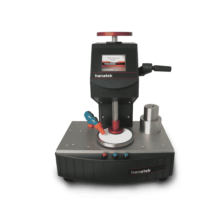
A laboratory Rub Proof Tester is a tool for comparing the rubbing, scuffing and marking of inks and coatings on commercial print and packaging, it can be used as part of quality control in a production environment or as an aid to development in the laboratory.

Protective packaging, magazines, labels and promotional material are all printed with inks and coatings which are designed to remain clear, bright and undamaged during the items lifetime.

Unfortunately movement during packing, shipping or everyday handling can cause items to mark or scuff. The coatings and substrates used, the cure conditions and the amount of abrasion all affect the severity of this damage.

Modern papers and carton boards can prove a challenge for inks and coatings, harsh substrates such as matt paper and recycled board are prone to marking, scuffing and rubbing during post-print production and transportation.

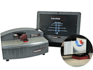
The Hanatek ink rub tester allows the user to compare the durability of printed cartons, commercial print or proofs of ink and varnish on a wide range of substrates.

The instrument uses a rotary motion to abrade the printed surface against a smaller sample of the same printed surface or a reference white material.  To mimic the effects seen in a production environment, the test can be performed as a ‘face to reverse’ also.  The user can vary the abrasion force and the number of cycles to adjust the severity of the test.  More information on test procedures can be found in BS3110.

The Hanatek rub tester replicates the test method used on older style instruments such as the Pira Wallace rubproofness tester but benefits from the inclusion of digital weight and cycle selection, assuring accurate unsupervised abrasion testing.

Who Measures Board Stiffness and Crease Resistance?

Board stiffness and crease resistance are important measures that indicate how a finished carton will run on an automated glueing, filling or packaging line.

Substrate manufacturers, printers, converters and any manufacturer who fills or packs products in cartons can use this measurement to optimise production.

QA departments use these instruments to check the running attributes of finished cartons prior to conversion and filling, reducing lost production time from slow running or difficult to convert packaging.

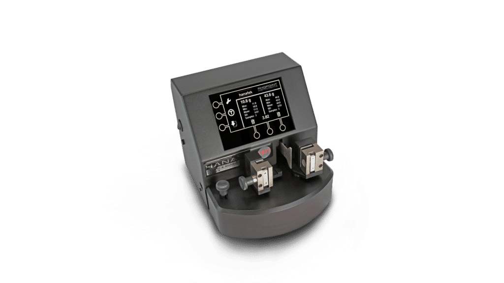
Carton manufacturers and designers can use a CBT1 crease and board stiffness tester with a Hanatek Carton Crease Proofer to test different substrate and crease combinations in the laboratory without committing valuable production time.

Why is board stiffness testing and crease resistance testing important?

A printed sheet or roll of carton board is die-cut and creased into a preformed carton board blank.
This blank is then often glued and erected before being filled on an automated packaging line, these processes all interact mechanically with the blank to convert it into a three-dimensional object.

To be most cost-effective, it is important this conversion is performed at the maximum speed possible without causing misfeeds and blockages in the process.
It is also important that the finished material has the required dimensional strength to hold and protect the packaged product.

Board stiffness test and crease resistance testing are important parameters that help determine maximum conversion and packaging speeds, they can also be related to the final dimensional stability of the finished product.

Board stiffness is determined by the physical makeup of the substrate i.e. – its thickness, fibre mix, coating and manufacturing method. It is determined by measuring the resistance of a cut sample to a force applied through a pre-determined angle.

Crease resistance is a similar measure of resistance which is made across a preformed crease in the carton blank.

How is board stiffness and crease resistance measured?

The method for stiffness measurement is outlined in several international standards. These standards describe cutting a sample of pre-determined size either from a sheet of virgin material or from a pre-formed carton blank.

The sample is gripped in jaws and rotated through a set angle, and the force transmitted through the sample is measured. This force is quoted in grams for comparative measurements or g/cm2 -an absolute value for the tested substrate. Some instruments may also quote the value in mN or mN/m2.

Manual or Fully Automated Testing

The Hanatek CBT1 crease and stiffness tester is a low-cost manual instrument for testing board stiffness and crease resistance, the sample is clamped into the test jaws and the sample is rotated manually. The instrument displays the force measurement in grams and unlike other similar instruments on the market, it automatically calculates the crease to board stiffness ratio.  If multiple tests are conducted, batch statistics are displayed.  These can be printed for documented traceability.

For improved ease of use, a fully automated carton force analyser (CFA) should be considered, the instrument clamps the sample in electronically operated jaws and rotates the sample automatically at a pre-determined speed with pre-set dwell times.

The use of these operator-independent test methods vastly improves the repeatability of the results. The CFA also graphically displays the developing forces which gives added information on the physical changes that take place during bending.

Why is Film Thickness Important?

Plastic films are often used to encapsulate, protect and preserve products that are sold to consumers or industry. The film is used as a two-way barrier to stop product leaking out and also external contaminants from migrating in.

The effectiveness of the film as a barrier is related to its chemical composition and also its thickness.

Films which are below a specified thickness may fail physically- bursting, splitting or leaking, they will also be less effective at stopping the migration of oxygen and contaminants that can lead to product spoilage.

Who Measures Film Thickness?

Packaging developers and product manufacturers measure and specify the thickness of the film to ensure the robustness of the packaging and the functionality of the barrier.

Various test methods are used in this specification including burst testing, tear testing and various film migration tests. These tests, including thickness measurement, are repeated as part of Quality Assurance inspection throughout the manufacture of a product.

Using A Film Thickness Gauge

In contrast to this, film manufacturers need to ensure that a film, whilst conforming to a customers specification is also manufactured in the most cost-effective manner possible. By measuring and manufacturing within tight tolerances the amount of raw materials used can be significantly reduced, leading to improvements in productivity.

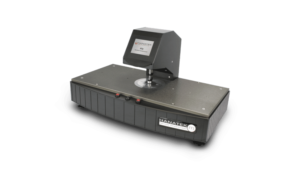
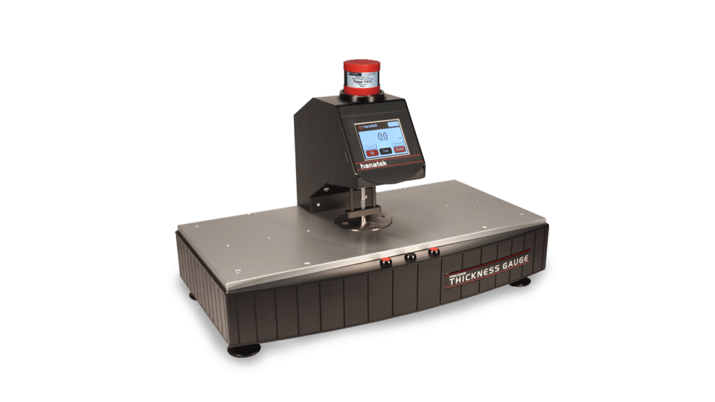
The Hanatek Precision Thickness Gauge (FT3) can also measure the thickness of paper, metallic foils, carton board, corrugated board, tissue, textile and any other packaging substrate.

Precision Thickness Measurement

Thickness is a key parameter for many manufacturers as it affects the functionality, quality and cost of finished products.

Functionality-  Raw material thickness directly influences the physical properties of a product. Important examples include;

  • Tensile strength of textiles, plastic films, paper and tissue.
  • Rigidity of plastic film, and cardboard packaging.
  • Barrier properties of plastic films.
  • Puncture resistance of plastic microwaveable containers.
  • Opacity of inks, coatings, plastic film and paper.

Quality- Thickness should be controlled to ensure batch consistency and ensure products have the correct tactile “feel”.

  • High-quality goods are packaged in robust high gauge materials.
  • Quality toilet tissue, baby wipes, and kitchen paper are supplied thicker and stronger.
  • Thicker, heavier paper is used for certificates, brochures and art supplies.

Cost-Using a low accuracy gauge inevitably leads to the supply of goods that are above or below thickness tolerance.

  • Out of tolerance material can be rejected by customers leading to huge re-working costs and loss of credibility.
  • A few microns saving in reduced thickness can equate to tens of thousands of Dollars/Pounds/Euros of raw material savings in a relatively short period.

The FT3 thickness gauge allows product to be manufactured within tight tolerances targeted right in the middle of a customer’s specification.

  • The high accuracy and resolution give absolute confidence that material is always supplied within customer requirements.
  • A high confidence in results often allows tighter manufacture control and a reduction in raw material use. Raw material savings can pay for the gauge in a matter of weeks or months.
  • Securely date and time-stamped result labels can be attached to retained samples or job sheets giving absolute confidence that a product has been tested throughout its production run.

How does the FT3 achieve high precision?

Sensor

The FT3 is uses a precision LVDT displacement sensor with highly stable electronics to produce a very sensitive transducer system.

Measurement Parameters-The key to repeatability and accuracy is to tightly control all the parameters that can lead to measurement uncertainty.
The parameters that affect thickness measurement are;

  • Measurement pressure.
  • Presser foot profile and size.
  • Measurement velocity.
  • Parallelism of presser foot to measurement plate.
  • Dwell time.

To allow manufacturers in the same industry sector to measure using the same conditions, these key measurement parameters are often specified by international standards (ASTM/ISO etc.).

External Factors

External effects such as temperature change and vibration will affect the measurement, the FT3 instrument is designed to reduce the impact of these.

Calibration

The FT3 has a multi-point calibration routine to reduce/eliminate the effect of non-linearity in the LVDT sensor.

Electronic Drift

The 0.01micron resolution instrument includes routines to reduce the effects of short term thermo-electronic drift of <0.1 microns.

Why do different applications have different measurement parameters?

Measurement Pressure

Many materials including plastic film, plastics, and rubber may crush or deform dependent on the pressure applied during testing and the momentum of the presser foot.

Textiles require high pressures during testing to remove wrinkles and airgaps.

Tissue thickness testing demands a light measurement pressure and slow presser foot speed so the paper fibres are measured without being crushed and flattened.

Tissue thickness testing demands a light measurement pressure and slow presser foot speed so the paper fibres are measured without being crushed and flattened.

It is clear that different industries have adopted measurement parameters that give meaningful results for their own application.

FT3 measurement forces are applied using fixed masses; each instrument is supplied ready to apply the exact force specified in the relevant international standard.

The FT3-V variable pressure thickness gauge can be useful if a sample needs to be tested to more than one standard, it can also be used to determine the compressibility of samples under different conditions.

Measurement foot size and profile

The measurement head size and profile is usually determined by the ISO Standard for the material.

  • Domed measurement head- Small areas can be measured with high resolution- Plastic films and coatings.
  • Small diameter flat measurement heads- used to apply a large pressure in a small area- Paper and board applications.
  • A large diameter flat foot – Measures the average thickness of fibrous material over a large area with light pressure – Tissue Paper. Opacity of inks, coatings, plastic film and paper.

Measurement velocity

The speed of the measurement head can also have an effect on thickness measurement. A fast-moving head will impact a sample with more energy and may deform or dent the material.

The measurement velocity of the FT3 head can be set by the user from 1 to 5mm/sec. This speed is sometimes specified in international standards.

The most significant source of measurement error in any system is often introduced by the human operator.

The FT3 family of instruments have a number of features that reduce the impact of a human operator.

Fully automated operation

the main parameters are fully controlled by the instrument; measurement pressure, speed and dwell time.

Onboard statistical calculation

Mistakes are often made in transcribing results and calculating statistics, these functions are performed automatically by the instrument.

Results can also be output via RS232 to SPC programs, lab networks or MS Excel.

QA labels record results throughout the batch

Securely time and date stamped labels with statistical results can be produced throughout a batch run and attached to job cards or retained samples. This traceable control gives the customer confidence that the whole batch of product is within specification and allows manufacturers to issue certificates of conformance.

Standards of Conformity

The FT3 family of instruments comply with a variety of ISO & ASTM standards for many different applications including:

Paper & Board

  • ISO 534
  • ISO 3034
  • DIN 53105
  • BS EN 20534
  • BS 4817
  • ITAPPI T411
  • SCAN P7
  • SCAN P31
  • FEFCO No 3

Plastic Film

  • BS 2782-6
  • DIN 53370
  • ISO 4593
  • ASTM D6988

Textile

  • ISO 5084

Tissue

  • ISO 12625
  • BS 7387
  • SCAN P47

Packaging Material Testing