
How to Measure with Boring Thickness Module
This guide describes the standard, automatic workflow for measuring layer thicknesses on a Säberg-drilled multi-layer coating sample. For manual placement or editing of the ring boundaries, see Boring Thickness Manual Mode.
Before You Start
- A Säberg drill bit of a known cone angle has been used to prepare a clean conical crater through the coating stack down to (or close to) the substrate.
- The Aesthetix device is connected, calibrated, and listed in the device manager.
- The drilled site is clean and free of dust or drill swarf.
Step-by-Step
Open the Boring Thickness module
In the Module Bar, select the Boring Thickness Module.

Enter the Drill Angle
In the right-hand properties panel, set the Drill Angle to match the cone angle engraved on the drill bit used to prepare the sample (for example 5.7°). Confirm by pressing Set.
See Boring Thickness Parameters for details on every parameter.
Place the instrument on the sample
Position the Aesthetix flat over the drilled crater so the crater is centred and entirely visible in the live image.
Optimise the camera exposure
Press the Auto-Exposure button (the "A ±" button below the live image). All rings should be clearly visible with sharp contrast between adjacent layers. Set the Marker color, this will enable the detection of the outer circle.
Enable Center Lock (recommended)
For a correctly drilled, concentric crater, enable Center Lock in the properties panel. This forces every detected ring to share the same center point and improves consistency.
Run automatic ring detection
Press the Auto button. Appearance Elements takes a preview measurement and places one circle on each detected ring boundary.
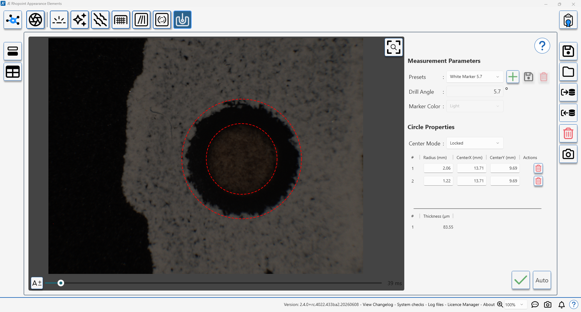
Verify the detected rings
Inspect each detected ring against the actual layer boundary in the image:
- If a ring is missing, add it manually — see Boring Thickness Manual Mode.
- If a ring is misplaced, select it (single click on the ring outline) and drag its edge to align it, or edit Radius / Center X / Center Y directly in the ring list on the right.
- If a ring was detected on a feature that is not a layer boundary (dust, scratch, drill swarf), remove it using the trash icon in its row.
- Coating or Layer Thickness is calculated below the Circle properties
Run the measurement
Press the Tick button. Appearance Elements saves the layer thicknesses from the current ring radii and the Drill Angle to the measurement table.
Inspect the result in the table
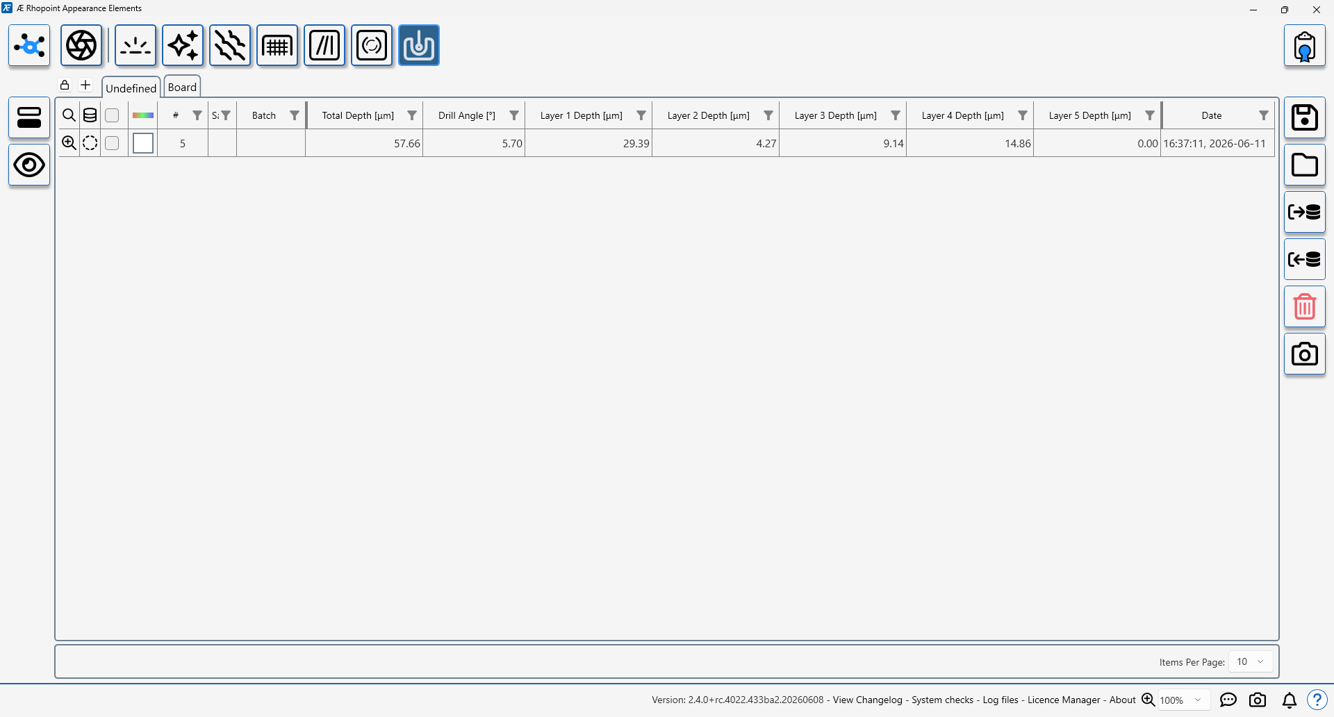
Return to the table view (Navigate to Table View button). The measurement appears as a row with Total Depth, Drill Angle, and individual Layer 1–5 Depth columns.
Expanding the row reveals the drill image, the overlay with numbered rings, and a per-layer thickness table.
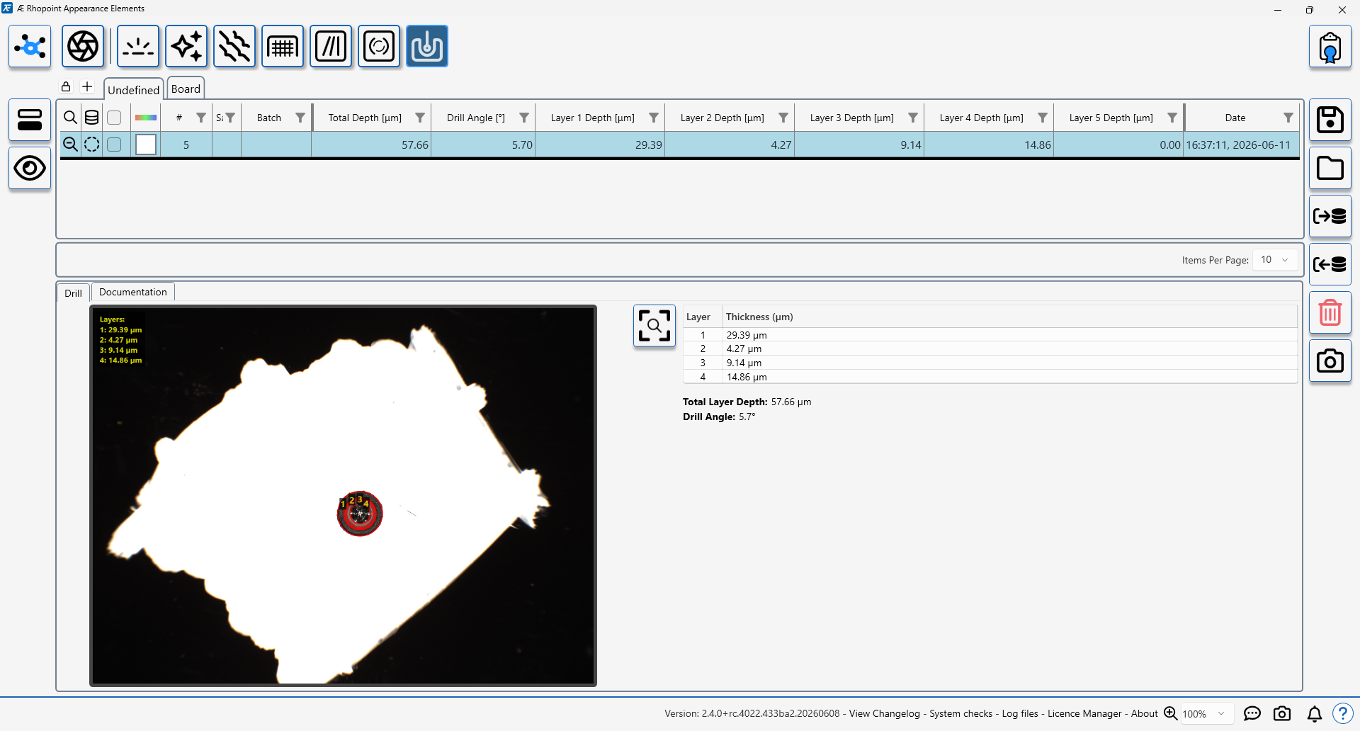
Tips for a Good First Measurement
- Always perform an Auto-Exposure first; an over- or under-exposed image will both confuse automatic detection and hide subtle layer boundaries.
- The outermost ring corresponds to the top of the coating system (Layer 1 = topcoat); the innermost ring corresponds to the bottom of the deepest measurable layer.
- The module supports up to five layers in the data table (Layer 1 Depth … Layer 5 Depth). Drilling six or more visible rings is technically possible but additional layers will not be stored as separate table columns.