
Boring Thickness Measurement Guide
This guide collects best practices, common pitfalls, and troubleshooting steps for the Boring Thickness Module. For the standard workflow see How to Measure with Boring Thickness Module, and for manual placement see Boring Thickness Manual Mode.
Sample Preparation
The quality of the boring measurement depends almost entirely on the quality of the drilled crater. Aesthetix can only measure what is visible in the image.
- Use a sharp, clean drill bit. A worn bit produces an irregular cone and frayed layer edges.
- Drill at a stable, perpendicular angle to the coating surface. A tilted drill produces an elliptical crater whose rings are no longer truly concentric and whose radii do not match the cone geometry — the calculated thicknesses will be biased.
- Drill deep enough to reach into the substrate. The outermost ring must correspond to the original coating surface; the innermost ring must lie clearly within the deepest layer (or in the substrate itself).
- Clean the crater with a soft brush or compressed air. Drill swarf and dust create false features that confuse automatic detection.
Imaging the Crater
- Always run Auto-Exposure before measuring. Boundaries between layers of similar colour are very sensitive to exposure.
- If the coating colours are such that an inner layer is darker than the layer above it (for example, dark primer under a lighter topcoat), enable Invert Image in the properties panel — see Boring Thickness Parameters.
- Centre the crater in the live image. Rings near the image edge are subject to greater lens distortion and their radii will be slightly biased.
Choosing the Drill Angle
The Drill Angle parameter must exactly match the physical angle of the drill bit used. Common bits are engraved with their angle.
| Drill Angle | Magnification of layer thickness |
|---|---|
| 5.7° | × 10 (Δr × 0.0997 ≈ Δr / 10) |
| 10° | × 5.67 |
| 20° | × 2.75 |
| 30° | × 1.73 |
Smaller angles "stretch" thin layers over a wider radial distance and are preferred for thin coatings; larger angles concentrate the crater and are preferred for thick coatings on small samples. See Drill Angle in the glossary.
Center Mode — When Locked and When Free
- Locked (recommended default): Use for any correctly drilled, geometrically concentric crater. Center Lock removes subpixel detection noise that would otherwise produce slightly offset rings.
- Free: Use only when you deliberately want to follow visibly non-concentric rings, for example to investigate a tilted drill or an asymmetric crater.
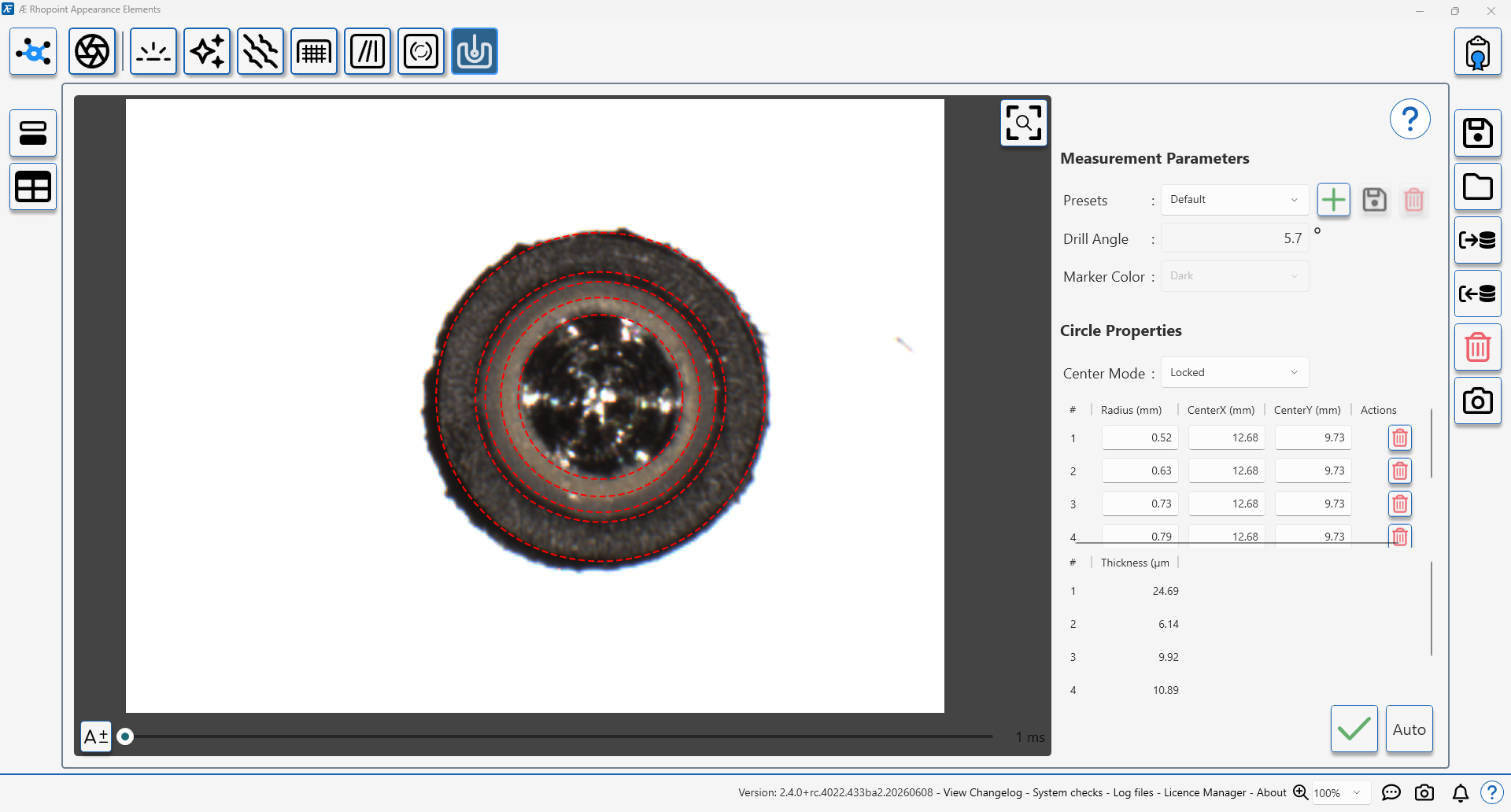
Verifying the Result
After the measurement is calculated, the overlay shows numbered layer labels between adjacent rings and a "Layers:" summary in the top-left corner of the result image. Cross-check:
- Layer count. The module produces N − 1 layers from N rings. If you expected three layers but the table shows two, one ring is missing.
- Plausibility of values. Typical decorative paint layers are in the range of 10–80 µm; primers may be 20–60 µm; industrial heavy-duty coatings can reach several hundred µm. Values orders of magnitude off this range usually point to a wrong Drill Angle.
- Total Depth. Compare the total depth to an independent non-destructive thickness measurement on the same sample, if available.
Troubleshooting
| Symptom | Likely cause | Fix |
|---|---|---|
| Automatic detection finds no rings | Crater too dark, too bright, or filled with swarf | Re-run Auto-Exposure; clean the crater; try Invert Image |
| Automatic detection misses one ring | Low contrast between two adjacent layers | Add the missing ring manually — see Boring Thickness Manual Mode |
| Rings slightly offset from each other | Subpixel detection noise on a concentric crater | Enable Center Lock |
| Rings clearly off-centre | Drill held at an angle, crater is elliptical | Re-drill perpendicular; results from a tilted crater are biased |
| Layer thicknesses one order of magnitude wrong | Drill Angle parameter does not match the physical bit | Check engraved angle on the bit; correct the Drill Angle in properties; press Set |
| Layer thicknesses are wrong but proportional | mm/pixel calibration of the Aspec camera is off | Recalibrate the device — see the calibration section of the Aesthetix manual |
| More than five visible layers | Module table stores only Layer 1–5 Depth | Plan ahead: drill only the layers you need to resolve, or export the raw layer depth list |
When Not to Use This Module
- For routine total dry-film thickness on a known coating, a non-destructive magnetic or eddy-current gauge is faster, non-destructive, and sufficient.
- For very thin coatings (< 5 µm total) the radial spread of the rings is below the lateral resolution of the Aspec camera and the measurement becomes unreliable.
- For samples where the substrate is not visually distinguishable from the deepest coating layer, the innermost ring cannot be placed reliably.