
Boring Thickness Manual Mode
Manual mode lets you place, move, resize and remove ring boundaries by hand. Use it when automatic detection misses a layer, places a ring on a non-boundary feature, or fails entirely on low-contrast samples.
The procedure described in How to Measure with Boring Thickness Module applies up to the point where you would press Auto. From there, replace step 6 with the manual workflow below.
Drawing a Ring
The way you create a ring depends on whether Center Mode is Locked or Free — see Boring Thickness Parameters for the parameter itself.
Center Mode Free — Edge-to-Edge Drawing
- Click on the live image at one edge of the ring you want to capture.
- Hold the mouse button and drag to the opposite edge of the same ring.
- Release the mouse. A ring is created whose diameter equals the distance between the two click points.
This mode is intended for asymmetric craters or for samples where you want to follow each visible ring exactly.
Center Mode Locked — Radius from Reference Centre
- Make sure at least one reference ring (the first ring in the list) already exists. If none exists, draw it first with Center Mode temporarily Free, then enable Locked again.
- Click anywhere on the rim of the next ring.
The new ring is created with the same centre as ring #1 and a radius equal to the distance from the centre to the click point.
This mode is the recommended workflow for a correctly drilled concentric Säberg crater.
Selecting a Ring
Click directly on the outline of an existing ring. The ring turns blue and a dashed bounding box with five interactive nodes appears:
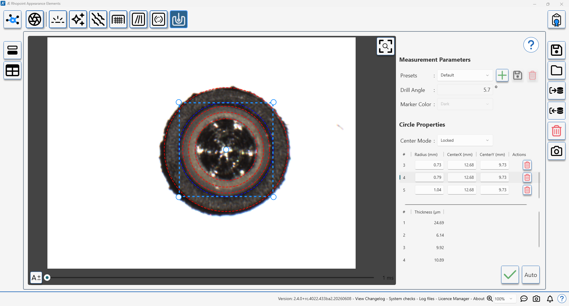
- Centre node — drag to move the ring (with Center Lock on, all rings move together).
- Four corner nodes — drag to resize the ring. The ring stays circular (width and height are kept equal).
Editing Ring Values Numerically
The ring list on the right of the module shows every ring with its Radius, Center X and Center Y in millimetres. These fields are directly editable: click into a cell, type the new value, and press Enter. Use this when you have an external reference for the expected ring radii (for example, a calibration standard).
The # column is the ring order. The order can be changed by drag-and-drop within the list; this affects only the display, not the measurement.
Removing a Ring
Click the trash icon in the ring's row in the list. The ring is removed from the image and the remaining rings are renumbered automatically.
Recommended Manual Workflow
- Open the Boring Thickness module and set the Drill Angle (see Boring Thickness Parameters).
- Place the instrument on the sample and run Auto-Exposure.
- Decide on Center Mode — Locked for a correctly drilled crater, Free for an asymmetric one.
- Draw or auto-detect the rings.
- Edit any misaligned rings using the bounding-box nodes or the numerical fields in the ring list.
- Visually verify that every ring sits exactly on a layer boundary and that no spurious rings remain.
- Press the Tick button to save the measurement.
- Review the overlay and accept or reject as in step 9 of How to Measure with Boring Thickness Module.
When to Prefer Manual Mode over Auto
- The coating has low inter-layer contrast and automatic detection misses layers.
- The crater has visible imperfections (drill marks, swarf, dust) that automatic detection picks up as false boundaries.
- You are calibrating against a reference sample with known ring radii and want full control.
- You only want to measure a subset of the visible layers (for example, only top and bottom).