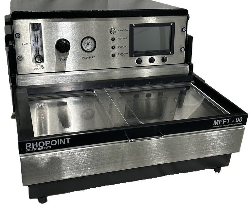
Rhopoint MFFT
MINIMUM FILM FORMING TEMPERATURE BAR - MFFTB
RHOPOINT INSTRUMENTS LTD
Rhopoint House
Enviro 21 Park
Queensway Avenue South
St. Leonards-on-Sea
East Sussex, UK
TN38 9AG
Phone: +44 1424 739622
Fax +44 1424 730600
Specification
- Platen: Copper, nickel plated
- Platen Dimensions: 483min x 235min
- Parallel Tracks: Using 1'' cube applicator (maximum 10)
- Weight: 38kg (85 lb)
- Dimensions: 550mm wide x 350mm high x 610mm deep
- Temperature: Digital readout of temperature.
- Interface: LCD touchscreen, temperature cursor
- Output: PDF report
- Indication: LED indicators- heating, cooling, coolant failure
- Alarms: Audible and visual for water flow failure.
Services required
- Mains: 220 240 volts AC / 110 120 volts AC
THIS INSTRUMENT MUST BE EARTHED - Air: 4 litres/min at 100 psi.
- Water: Normal mains supply or recirculation and chiller unit
- Water Temperature: 15°C maximum for lowest temperature range operation.
- Water Drain: Gravity
Accessories
The MFFTB is supplied complete with the following;
- MFFTB Instrument
- Mains cable
- Air connector
- Water connectors
- Cube applicator 75um x 1'' cube
- Quantity desiccant
- Quantity indicator crystals
- Five hypodermic type dispensers
- Spare fuses
Optional Extras
- Additional cube applicators
- Re-circulating water unit
Minimum Film Forming Temperature MFFT
The "minimum film forming temperature" has been described as "the minimum temperature at which a water borne synthetic latex or emulsion will coalesce when laid on a substrate as a thin film. When this process occurs, in the absence of pigmentation or other opacifying materials, a clear transparent film is formed. At lower temperatures than the minimum, a white, powdery, cracked film will result''.
The minimum film forming temperature is usually closely related to the glass transition temperature (Tg) but not synonymous with it; whilst the Tg may be determined by predicted calculation, the minimum film forming temperature is best determined by the use of a MFFT Bar, the basic principles of which are described in ASTM D2354. Early instruments were usually cumbersome, inaccurate and slow to achieve equilibrium.
Principle of Operation
A nickel plated copper platen is electronically cooled at one end and warmed at the other end. Air or nitrogen is caused to flow over the surface, from cool end to warm end as a uniform blanket. To achieve the required degree of uniformity the air or gas is delivered via a carefully designed sintered distribution block; the design is such that freezing does not take place at the inlet.
For use with air, a drying system is incorporated into the housing together with a flow controller. The air dryer contains indicator crystals, which are clearly visible in a transparent container. The complete air conditioning system is readily accessible at the side of the instrument.
Water at normal mains pressure removes the excess heat from the coolers. Quick release couplings are provided. Water is normally drawn from a laboratory tap and the outlet is run to drain by gravity. Alarms, both audible and visual are actuated in the event of cooling water supply failure.
Temperature sensors are mounted under the surface of the platen. These are used to control the temperature of the platen in accordance with the chosen range. They are also used in conjunction with the temperature cursor to indicate the platen temperature at the MFFT point.
A hinged clear plastic cover over the platen provides thermal insulation whilst allowing visual inspection of the determination as it progresses. The transparent temperature cursor is mounted on the cover to identify the exact film forming temperature.
Instrument Overview
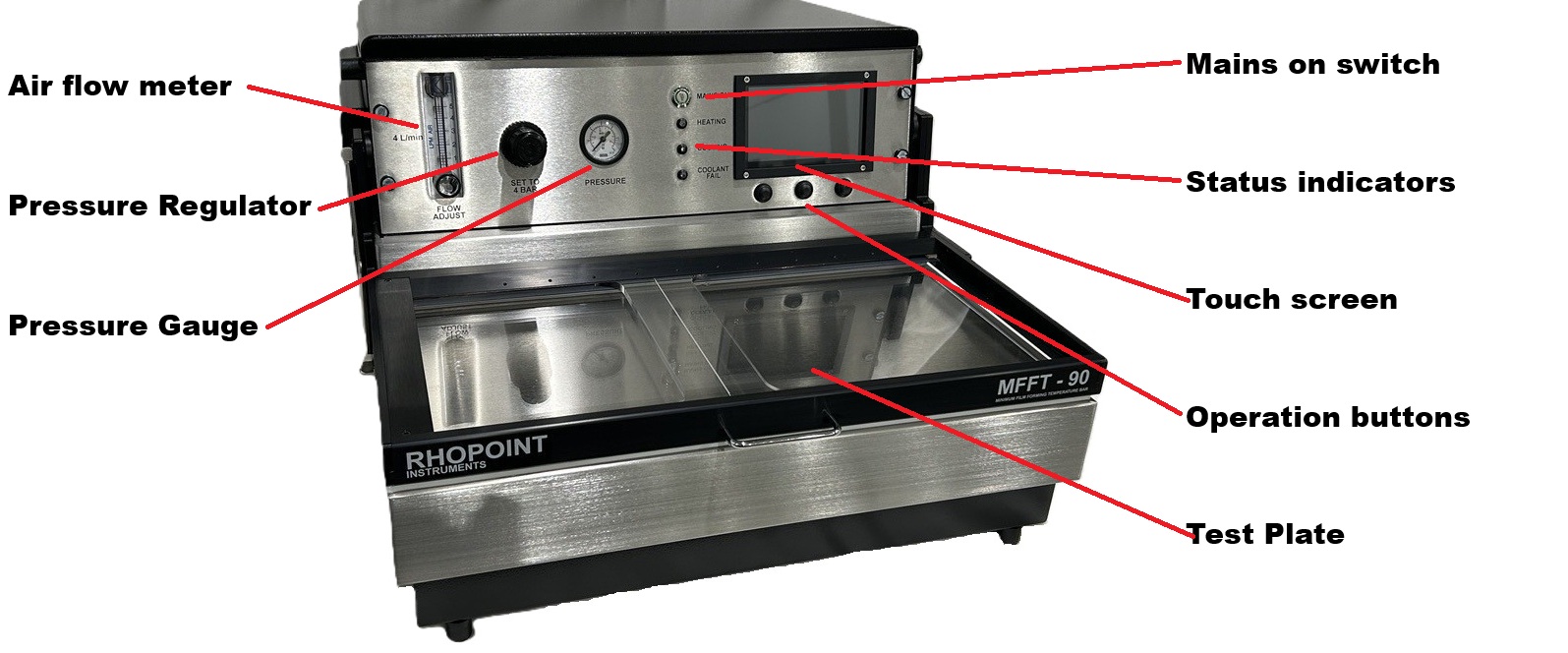


Below the touch screen display are 3 physical buttons. These buttons replicate the operation of the on screen buttons above them. These physical buttons will cover basic operation and are easier to use with protective gloves. They also easier to clean if product is accedently transferd to them.
Pre-operating Setup
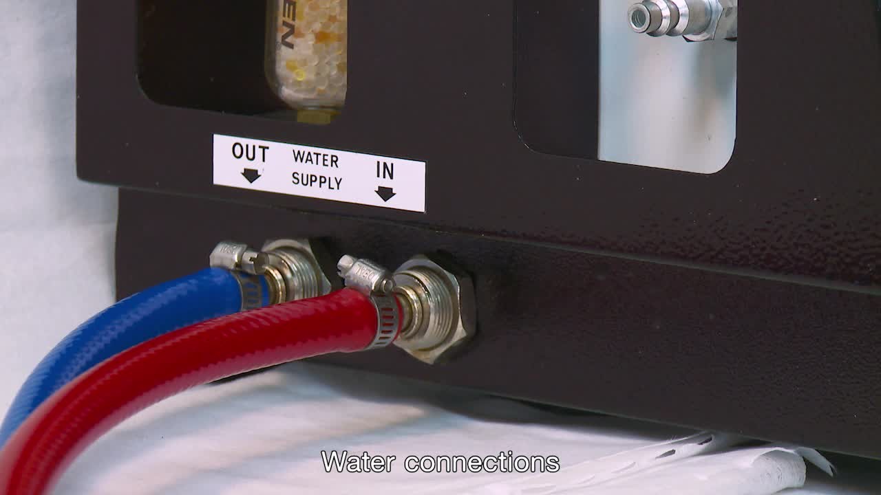
Connect water feed
Cold mains water or recirculating chiller and water drain.
WATER IN is right spigot, left spigot is WATER OUT.
Water pipes and connectors are supplied with the instrument.
INFORMATION
Cut the tap connectors from the supplied hose.
Using the supplied spare hose clamps secure the hoses to the chiller.
OUT on the chiller is connected to IN on the MFFT.
IN on the chiller is connected to OUT on the MFFT.
Example chiller connection.
.jpeg)
If using a water chiller do not turn on the chiller until the instrument has powered up. A circulating bypass loop will activate once the instrument has booted up. Chiller mode must be activated in the instrument menu.
If using mains water supply the water can now be turned on.
Disconnecting the water feed
Check that the water feed to the instrument is turned off.
Push the outer collar in and at the same time pull the hose out.

Connect air feed
Air feed pipe and connectors are supplied with the instrument.
Push the airline connector onto the spigot on the instrument.
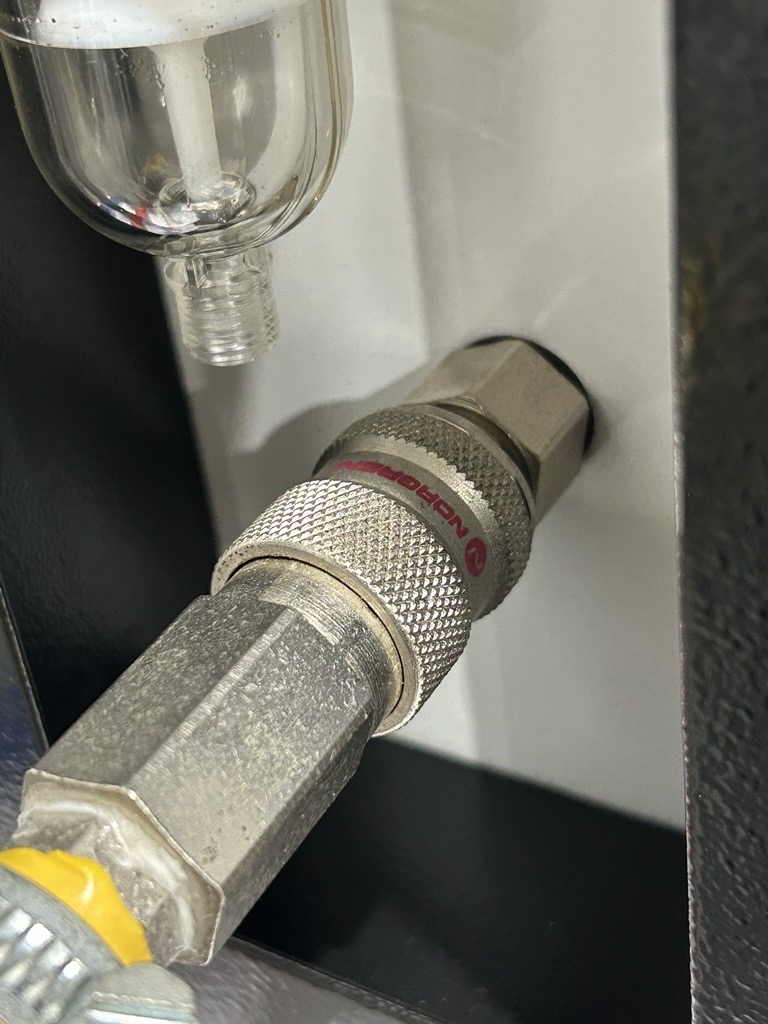
Airline removal
To remove the air feed pull the collar back, the coupling will release.
Air flow setting
Set the pressure to 4 bar using the pressure regulator. Set the air flow to 4L/min using the flow controller.
.jpeg)
Connecting the mains supply
Plug in mains 240V 50Hz or 115V 60Hz dependent on model. The mains in socket is located on the side of the instrument. Mains leads are supplied with the instrument.
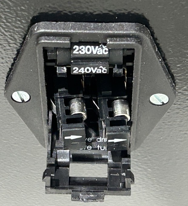
Changing the operating voltage
The instrument will operate on 240V 50Hz or 115V 60Hz and will come pre-configured from the factory. The operating voltage selection can be changed. With the instrument unplugged, use a tool such as a flat head screwdriver to open the compartment, it will hinge down from the top.
Remove the voltage selection drum. Rotate it to the desired setting and re-insert. Hinge the cover back into place and push firmly to latch back into place.

Operating the Instrument
Press the power button on the front of the instrument.
The green switch surround will flash, indicating the instrument is booting up.
Once booted the introduction screen will be displayed. The switch surround will stay illuminated green.

Press the play button or the below physical button to progress to the main operating screen.
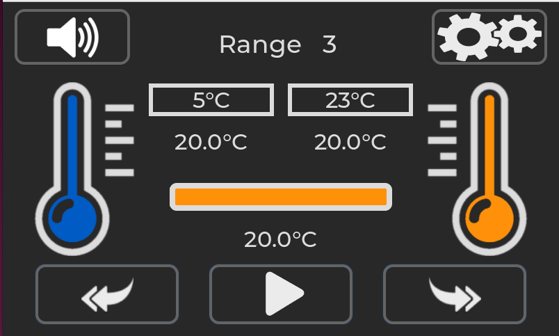
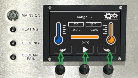
The main operating screen for the MFFT instrument will look like the above. In this example range 3 has been selected but the instrument is not set to start achieving target temperature.
Settings Menu


Used to enter calibration and factory options

Used to adjust the instrument time and date

Used to access links to an online manual.

Maintenance menu
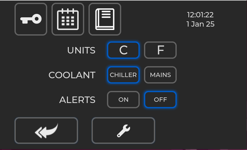
UNITS
Change the instruments displayed temperature between Degrees Celsius or Degrees Fahrenheit.
COOLANT
Change the water coolant type between chiller mode and mains mode.
Chiller mode should be used If the instrument is being used with a recirculating water chiller. When a coolant is not required an internal bypass valve will open so that the water flow is not stopped. This avoids the pump in the chiller from being deadheaded that can lead to permanent damage.
Mains mode should be used when the instrument is being used with mains water. The internal bypass valve is deactivated so that only water is taken when required.
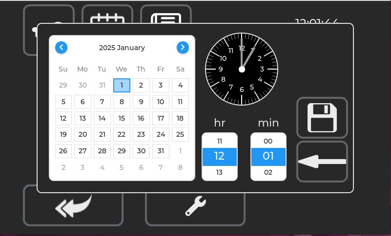
Setting the Time and Date
Use the onscreen menu to set the internal time and date of the instrument. When complete press the save button
Maintanance Menu
The maintenance menu contains information about the instrument and feedback from various sensors. It will help diagnose any issues with general operation.
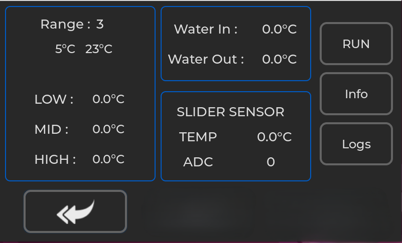
Range
The current range selected in the instrument. Target temperatures are shown.
LOW, MID, HIGH
Readings from the temperature sensors mounted on the reverse of the test plate.
Water In, Water Out
Readings from the temperature sensors mounted on the water inlet and the coolant heatsink.
Slider Sensor
Temperature of the test plate at the location of the slider and the feedback from the sensor.
RUN/STOP
Will start and stop the instrument temperature regulation.
Info
Shows information about the instrument. Serial number, service date and hardware variant.
Logs
Exports logs from the instrument for diagnostic purpose. Note a USB must be connected to export the logs.
Main Operation
Main screen overview
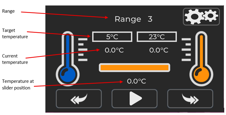
The main operating screen for the MFFT instrument will look like the above. In this example range 3 has been selected but the instrument is not set to start achieving target temperature.
To change the target range, press the back or return button
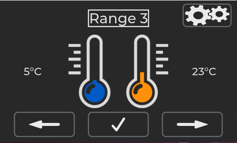
Press the left of right arrow buttons to cycle through the range options.
![]()
![]()
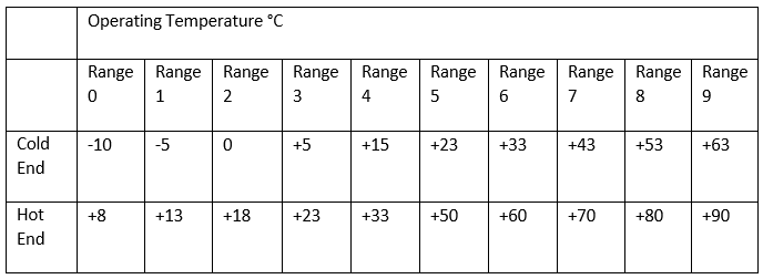
The MFFT instrument has 10 operating ranges. Range 0 – 9. Target Cold end and Hot end for each range is shown in the table below.
When the desired range has been selected use the tick button to confirm the selection.
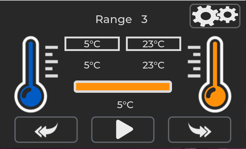
With the desired range has been selected press the play button.
The heating and cooling process will start.
The play button will change to a pause button.
Pressing the pause button will stop the heating and cooling process.
When the target temperature is reached the thermometer outline will turn green, indicating correct temperature.
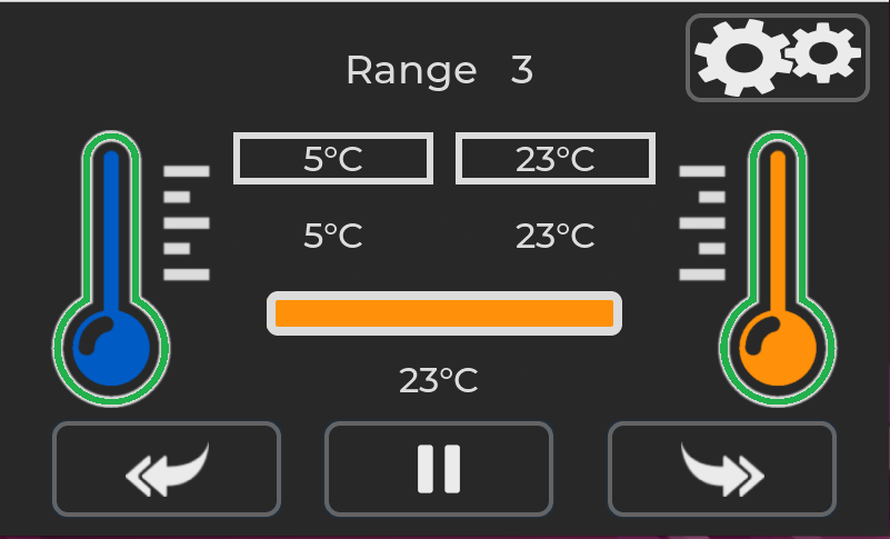
An audio system ready beep will also sound. To mute the audio alert the speaker icon can be pressed.

Pressing the right-hand double arrow button will progress to the next screen. 
The plate temperature will continue to maintain at the set points. The sample to be tested can now be placed on the test pattern.
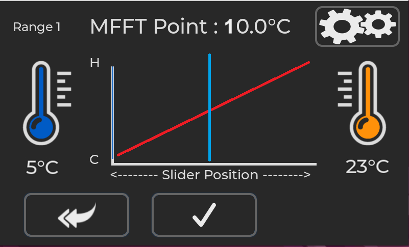
The screen will now show the hot and cold set points and the MFFT point.
When the sample has dried, move the cursor to the MFFT point.

When the cursor is at the correct position press the tick button to accept the values.

The results of the test are displayed on the screen.
Press the return button to exit back to the main range stabilization screen.
Press the save button to export the results to a CSV file.
A csv file will be saved on a USB drive if inserted. The USB port is on the rear of the instrument.
Example of the CSV file
Serial Number,MFFT123456
Date,21 Aug 2025
Time,13:52
Range,9
Cold,63
Hot,90
MFFT Point,72
Powering off the Instrument
Press the power button on the front of the instrument.
The green switch surround will flash, indicating the instrument is shutting down.
The shutdown procedure can take up to one minute.
Applying the Sample
PRE TEST CHECKS
Check that the platen is clean and free from grease.
Check that air dryer indicator crystals are orange.
If green, change crystals; unscrew transparent container, empty refill with activated alumina and gel indicating crystals. Spare air drying and crystal mix is supplied with the instruments. Additional spares are available from Rhopoint.

Apply emulsion using 75 micron cube applicator from warm end right to cold end left, or in U-Shaped form starting and finishing right hand side.

RECOMMENDED
Apply a control strip using emulsion of known MFFT is recommended .
All coatings should be applied within ten minutes. If there is a delay in applying a track, close the cover to prevent ice formation, reopening the cover as soon as the next coating material is ready.
The use of several applicators is recommended if more than one emulsion is to be applied. Pre-fill hypodermic type dispensers with emulsion to further reduce preparation time.
Close the Perspex cover.
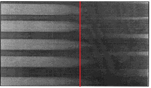
Periodically check the films, film formation time depends on temperature but all films should be formed in approximately 1 hour.
When films have formed (see illustration) set the temperature cursor to read point on track where the film has coalesced over 90% of the track width.
PIGMENTED EMULSIONS
The MFFT bar is sometimes used for tests on pigmented emulsion, where the MFFT determination is more difficult because there is no clearly defined change in "colour" of the coalesced film.
There is, however, a slight change in the shininess of the surface and using a wooden spatula, lightly scraped on the surface, it is easy to define where the coalesced film stops and where the remaining film is poorly integrated and heavily cracked with very poor adhesion.
Cleaning
Immediately after use the platen should be cleaned; the most common method is to use a dilute detergent.
Solvents to the particular coating can be used.
Some users apply the coatings to self-adhesive plastic tape or film which has been laid on the platen. The temperature error due to the intervening layer is said to be about 0.1 °C. Cleaning is accomplished very quickly the method commends itself when the MFFT bar is used for production control.
Other users lay aluminium foil over the platen before testing. A few drops of glycerine placed between the foil and platen ensure good thermodynamic contact and allow the foil to be smoothed out evenly.
DO NOT USE ABRASIVES TO CLEAN THE TEST PLATE.
DO NOT USE CAUSTIC BASSED CLEANERS.
TEST ANY NEW CLEANING SUBSTANCES ON THE EDGE OF THE PLATE AWAY FROM THE TEST ZONE.
Replacing Fuses
The MFFT is protected from drawing too much current by two fuses, situated in a compartment above the mains input.
With the instrument unplugged, use a tool such as a flat head screwdriver to open the compartment. There are two fuse holders with white arrows on to indicate the direction. Slide these out, and test the fuses with a multimeter.
If the fuses have blown, replace them with the spares provided.
If the instrument still does not power up, or the fuses blow again, please contact your supplier for support.
EU Directive 2002/96/EC on WEEE
EU Directive 2002/96/EC on WEEE (Waste Electrical & Electronic Equipment) and RoHS (Restriction of the use of certain Hazardous Substances).
The European Union's Directive on Restriction of the use of certain Hazardous Substances in electrical and electronic equipment (ROHS) defines each of 10 categories of electrical and electronic equipment in Annex I . Category 9 is defined as follows:
Monitoring and control instruments
Smoke detector
Heating regulators
Thermostats
Measuring, weighing, or adjusting appliances for household or as laboratory equipment
Other monitoring and control instruments used in industrial installations (e.g. in control panels).
The RoHS Directive defines the scope of restrictions in Article 2 as follows:
"1. Without prejudice to Article 6, this Directive shall apply to electrical and electronic equipment falling under the categories I, 2, 3, 4, 5, 6, 7 and 10 set out in Annex IA to Directive No 2002/96/EC (WEEE) and to electric light bulbs, and luminaires in households."
This product is supplied as a Monitoring and Control instrument and as such falls within category 9 of the EU directive 2002/96/EC and so is excluded from restrictions under the scope of the RoHS Directive.
The Waste Electrical and Electronic Equipment Directive is intended to reduce the amount of harmful substances that are added to the environment by the inappropriate disposal of these products through municipal waste.
Some of the materials contained in electrical and electronic products can damage the environment and are potentially hazardous to human health; for this reason the products are marked with the crossed out wheelie bin symbol which indicates that they must not be disposed of via unsorted municipal waste.
Rhopoint Instruments Ltd have arranged a means for our customers to have products that have reached the end of their useful life safely recycled. We encourage all end users to us at the end of the product's life to return their purchase to as for recycling as per Article 9 of the WEEE Directive.
Please contact us on +44 (0) 1424-739622 and we will advise on the process for returning these waste products so we can all contribute to the safe recycling of these materials.